- 1
Application
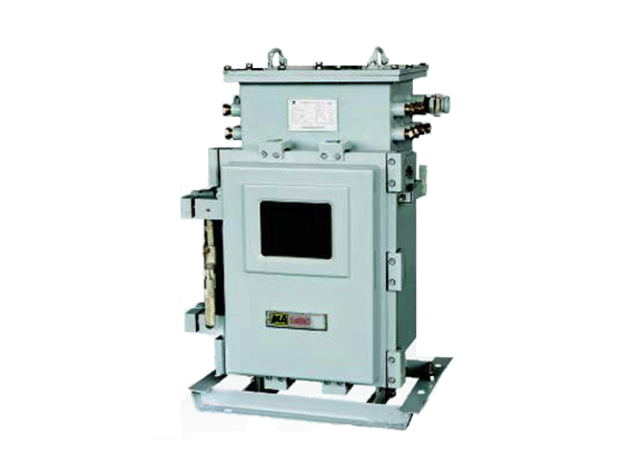
KJ512-F branch station of monitoring consists of industrial Ethernet switch, communication management machine, video coder, power supply panel, isolation fence, ups electrical source and explosion proof shell.
KJ512-F is designed for the transformer substation in the coal mine downhole. It is mainly used for the communication between the ground work station and intelligent comprehensive protection device to display the real-time electrical parameter, working status of the intelligent protection device and actualize the monitoring and control for the transformer substation.
At the same time, it will complete to transmit the data from the comprehensive protection device to the work station and transmit the control order from the work station to the protection device.
KJ512-F is installed a industrial Ethernet switch to form a double ring optical Ethernet. KJ512-F does not only take the communication with the comprehensive protection devices, but also access with an Ethernet interface video surveillance system and a PLC monitoring system which have a Ethernet. KJ512-F will send all the signals of the system to the ground workstation.
KJ512-F can work with a single double ring Ethernet or work together with all the existing Ethernet in the coal mine downhole.
Features
Powerful industrial level 32bit processor can work reliable.
Communication way is smart and it supports multi protocol, multi baud rate and multi communication way.
Adapting the real time operating software.
Communication and monitoring software is in plug-in modules which is an easy expansion and convenient to complete the data exchange between the protection devices and the ground attemper and monitoring system, and to achieve the focus local control center can continue to work for more than 2 hours and transmit the fault information to the ground workstation after power-down.
The optical switch is installed in the KJ512-F branch station. It is convenient to form an optical Ethernet ring.
This branch station support the remote maintenance and remote monitoring.
The LCD display screen will display all the record data of current, voltage, switch status and fault of transformer substation.
It can connect to the intelligent equipment.
Main technical parameters
Electrical source: AC127V, range: 75%-110%.
Power: ≤150VA.
Communication port: Ethernet port, double pair single mode optical port, SC port.
Sensitivity of reception: -28dBm (single mode signal, wavelength:1310nm)
Transmission distance: 10km.
RS485 or CAN transmission port of intrinsic safety signal: 4 way.
Transmission mode: master-slave, half-duplex, distance 1km.
General capacity: 32 end port at most.
Standby electrical source: 2 hours.
Working temperature: 0-40℃.
Dimension: 865(H)×586(W)×500(D)mm
Main function KJ512-F Mining Explosion-proof and Intrinsic-safety Power Supply Monitoring System
Data exchange function between protection devices and ground attempter and monitoring system.
It can receive and record the control order from the ground attempter center.
According to the order from the ground attempter center, it can collect the data of remote measure, remote communication, series fault record, tape-recorded wave data and transmit to the ground work station.
It has the open/close functions according to the order from the ground attemper center.
Monitoring function in local focus center
Monitoring the switch status.
Real-time display functions of current, voltage.
Recording and display functions for big accident.
Comprehensive selecting creepage function in the electrical circuit.
Cooperating with HRG-7RT/HRG-7FYRT comprehensive protection device complete selective single phase grounding function in the transformer substation to indicate that the grounding line and grounding phase have time function via fault record and signal.
Complete the time function from the attempter station to the comprehensive protection device. The main attempter station will check one time for each 30 min and the branch station will check for each 15 min to insure the time is same.
The branch station will monitor the real time working status of the comprehensive protection device. When there is a new protection device, the branch station will monitor the real time working status of the comprehensive protection device. When there is a new protection device, the branch station will be active to keep the tome same with the new protection device.
Conversion function of stipulations of an agreement.
Statute of plug-in expansion modules, you can easily access third-party smart device.
Remote maintenance function
Remote monitor the communication status, remote update the software, remote maintenance for data, remote download the tape record wave data, visit the branch station communication server to update the software and download the tape-record wave data via telnet or ftp.
Data storage function after power down: when the system is power down, the information and transmission will go on.
Monitoring of the communication status for each protection device.
When communication of the protection device is shut down, it will come into being a communication breaking record. This record will display and be sent to the ground attempter and monitoring center.
Real time monitoring all the operations of control.
The modification order from the main station for setting value: when the order is sent to the comprehensive protection device and the protection device is executed, the branch station will make a record.
The control order from the main station for the switches: when the protection device has a tape-recorded wave data, the branch station will ask this data from the protection device and form three file of hdr, cfg.
Main display screen for KJ512-F branch station
Monitoring open/close status of the switch: green means “close”, red means “open”.
Measuring value display: display the second time side current for each switch, the bus line will display three line-voltage and a zero voltage.
Protection signal indicating: when there are alarm signal or protection action signals, there will be a red signal in the related switch side.
When the signal is reset, the light will disappear. When the light is light, you can query the real non –reset signal by the menu of non-reset signal.
Communication status display: green light means “normal:, red light means “fault”.
Fault record display: it will display 10 fault record seriously in the nether of the screen. The time display mode is year-month-date hour: min: etc.


